LUC Power Board
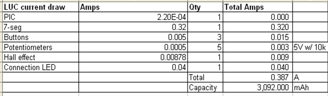
All the components could be run off 5V except the 7 segment displays. The displays had 4 LEDs in series, each dropping 1.7V for a total of 6.8V. The Tower Hobbies NiCd batteries supplied a nominal 7.1V and when fully charged were able to source 8.5V. We used this voltage to supply the 7 segment display directly, and used a 5V voltage regulator (LM7805C) to power the PIC and peripherals (potentiometers and buttons).
The LUC was required to last 8 hours on battery power. The chart to the right shows the current draw of each of the components on the board. The maximum current draw is 0.387A, most of which is being drawn by the 7 segment LEDs. To get 8 hours of use, we needed a battery capacity of 3092 mAh (Amps x 8hrs x 1000mA per Amp). The NiCd batteries had 1500mAh capacity, and placing them in parallel doubled the capacity to 3000mAh, which we deemed close enough to the required capacity. |

LUC Power Board
|
HZV Power Board
The LiPo batteries for the HZV needed to be disconnected at 9.8V to avoid damaging the batteries. To do this, a 5V voltage regulator powered a "Voltage cutoff" PIC. This PIC was in charge of reading an analog value from a voltage divider that reduced the nominal 11V battery supply to a manageable 5V range. When the analog value dropped below 0x40 (corresponding to 9.8V at the battery rail), the voltage cutoff PIC turned off a MOSFET connecting the ground pin of a second 5V regulator to the battery ground, effectively disconnecting power from the rest of the boat.
|

HZV Power Board
|
HZV PIC Board
The layout to the right depicts the 5 PICs used to control various components on the boat. We chose to use a PIC for each component due to the low cost of each PIC and the resulting simplicity in the code.
The board consists of PICs for:
|

HZV PIC Board
|
HZV Motor Driver Board
In order to drive the MACK 1885 motors we used the big brother to the L293, the L298 H-bridge Driver. During benchmarking tests, the motors drew 1.6A at 100% duty cycle and no load. The L298 can source up to 2A per channel, compared to the L293's 1A, and can handle supply voltages up to 50V. We ran both motors off of one L298 IC and controlled the voltage to the motors by sending PWM to the enable lines.
|

Motor Driver Board
|
LUC PIC board
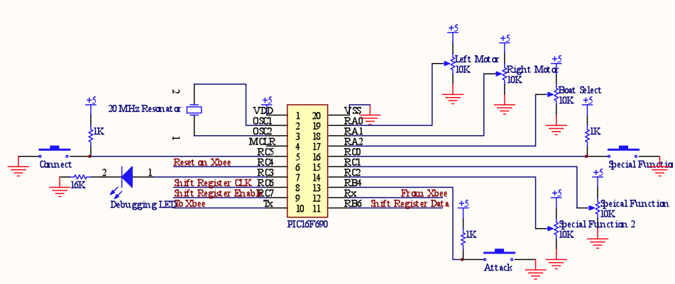
We used only one PIC on the LUC side. Inputs from the LUC were 3 button and 5 POT inputs. Each button had a 1K pull-up resistor. We had one debugging LED with a forward voltage drop of 1.7V in series with a 260K resistor, limiting the current through the LED to 12mA, well under the 80mA spec.
|
|
LUC 7-Segment Display Board
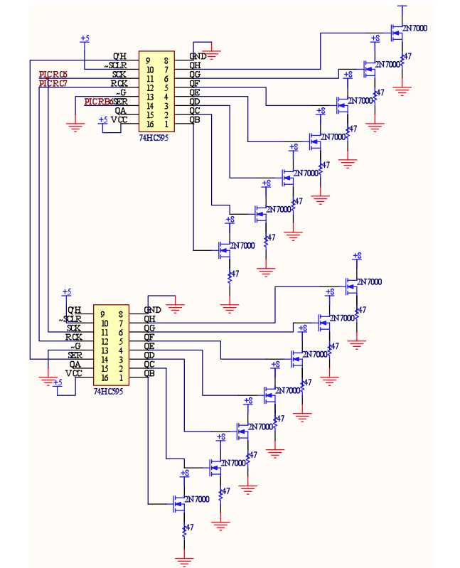
We drove two 7-segment displays through two 74HC595 shift registers. Each segment of the two 7-segment displays was run off of 8V, turned on through a 2N7000. The voltage drop across each segment had a typical value of 6.8V and a maximum forward current of 30mA. We chose a 47 ohm resistor to be in series with each segment based on these numbers
((8v-6.8V)/30mA = 40ohms). |
|
